Copy of Without circuits
This user’s guide demonstrates how to use the Without circuits option in TRAFOLO. Complex current distribution in inductors and transformers can lead to non-convergence while solving, especially at higher frequencies. This can happen in cases like solving for imported solid multi-turn windings at high frequencies, where the skin depth is significantly smaller than the wire cross-section. This issue can be mitigated, and convergence can be improved by skipping circuits. The Without Circuits option speeds up simulation and aids in faster convergence of solutions. This is done by applying voltage directly to the winding terminals, bypassing the need for circuit connections.
However, this method also possess some limitations. It does not allow solving with current excitation and this option is only available for full domain and inductance calculations.
Model setup
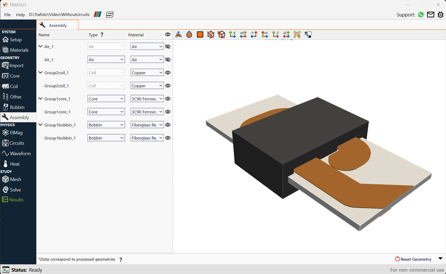
Consider a planar inductor made of an E core wound by a solid wire. Also, a fundamental frequency of 5kHz and harmonics of 50kHz are considered.
Ignoring Circuits
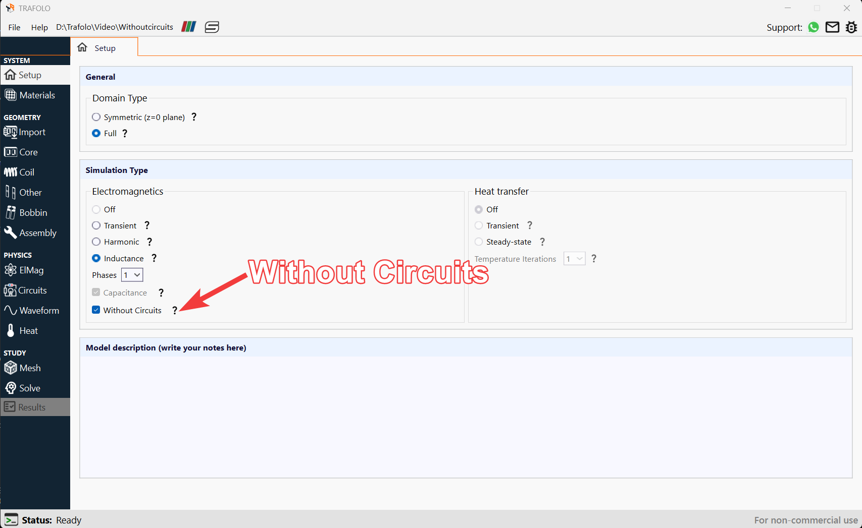
By selecting Without Circuits in the Setup tab, the solver ignores circuits and only applies voltage to external terminals.
Solving Process
Here the complexity of solving circuit equations coupled with the FEM windings is eliminated.
- In Primary Winding, Excitation is set to Urms[V] and Coil group connection type as Series.
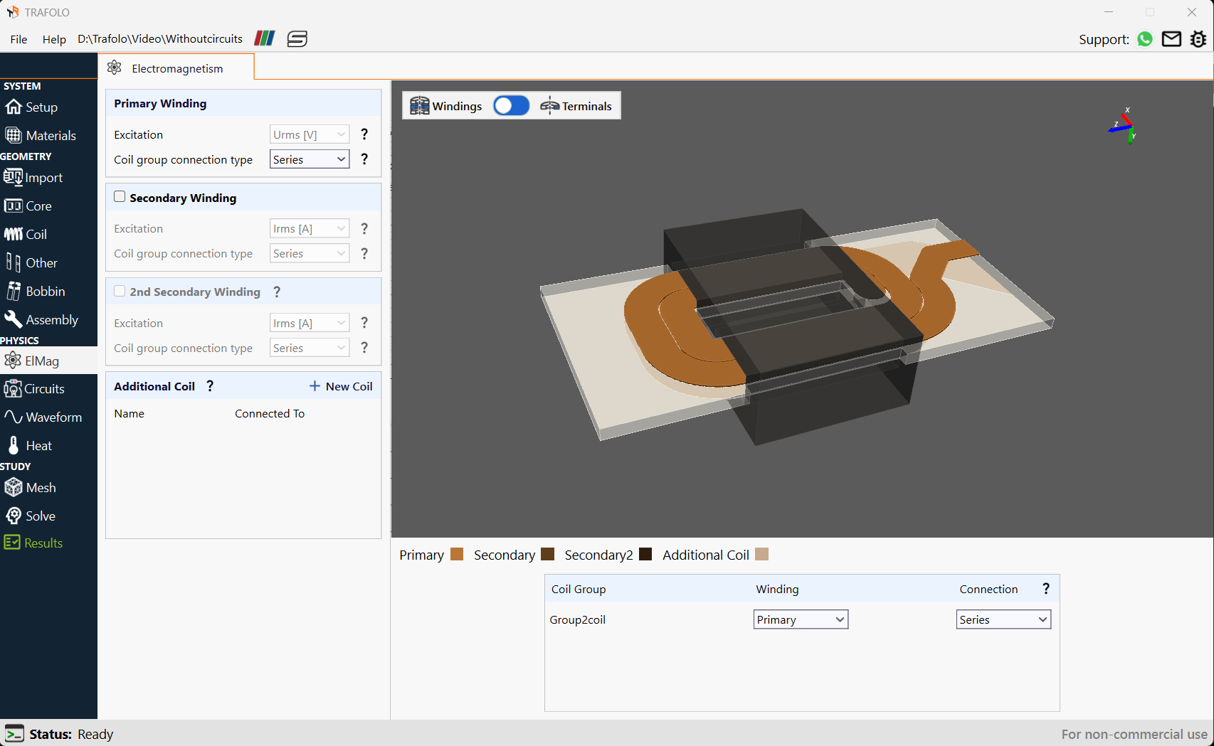
Note that in simulations without circuits, connections within and between coil groups will not function. By default, the Without Circuits setting connects all geometries within the same winding in parallel.
Simulation Parameters
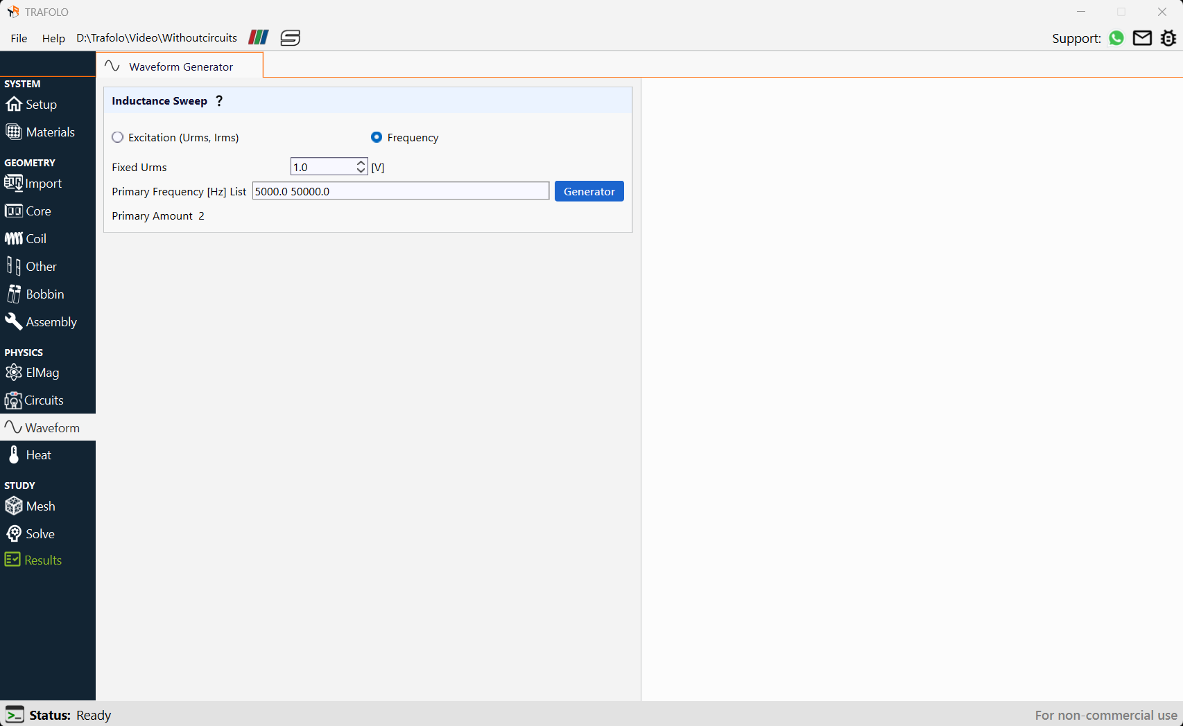
Parametric sweeps for voltage or frequency are conducted for analysis. Here we give fixed voltage excitation at varying frequencies.
- Set the Fixed Urms to 1V.
- Primary Frequency[Hz] List is given as 5kHz and 50kHz.
Analyzing Results for Without circuits
Inductance is analyzed in the Result tab.
Calculating Inductance
Results obtained using the Without Circuits option appear similar to those obtained with circuits. It is observed in this case that the inductance value remains constant with respect to frequency.
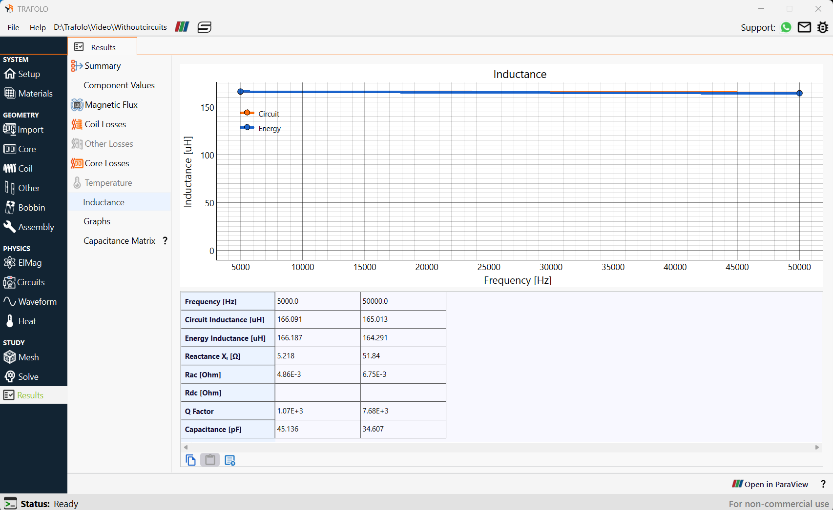
Inductance, Reactance, Rac, and Rdc resistance values are calculated.
The circuits method involves dividing complex voltage by complex current to extract impedance. Circuit current is obtained after the simulation by integrating current density on the terminal. The energy method involves integrating magnetic fields and dividing by the square of the primary current.